Step by step city modelling guide for urban planners

Urban planners, architects, and developers frequently face the same frustration: a project is technically sound, but stakeholders cannot visualise it. The gap between a planning document and a meaningful 3D representation can derail decisions, delay approvals, and undermine public confidence. Step by step city modeling closes that gap. This guide walks you through the full workflow, from collecting the right data to exporting a finished model ready for presentation and analysis, giving you a practical foundation for tackling city modeling projects with confidence and precision.
Key Takeaways
| Point | Details |
|---|---|
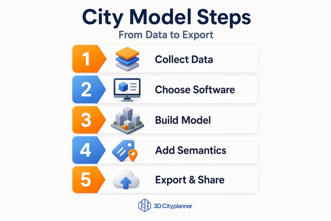
| Comprehensive preparation | Collecting accurate geographic and architectural data is essential for realistic city models. |
| Stepwise building process | Model terrain and infrastructure first, then design buildings, apply textures, and finally refine your model. |
| Semantic enrichment | Adding semantic data to models enables useful analysis and interactive digital twin capabilities. |
| Export for collaboration | Export the model in formats compatible with visualization and planning tools for stakeholder engagement. |
| Two-model strategy | Maintaining separate analysis and visualization models improves performance and functionality. |
Preparing for your step by step city modeling project
Building a solid foundation through preparation is essential before starting the actual city modeling process. Rushing into software without a clear data and requirements plan is one of the most common causes of rework and misaligned deliverables.
The first task is data collection. Gather diverse and accurate city datasets including satellite imagery, GIS data, architectural blueprints, and street-level images to ensure realism and accuracy. Each of these sources serves a different purpose. Satellite imagery establishes the macro-scale layout; GIS data provides coordinate-accurate geometry; blueprints inform building massing and floor heights; street-level photography guides texture and material choices.
Once you have your data, selecting the right software matters enormously. The correct tool depends on your project’s purpose, team capabilities, and the Level of Detail (LoD) required. LoD is a standard urban modelling concept where LoD1 represents simple block shapes, LoD2 adds roof forms and basic facades, and LoD3 delivers detailed architectural models. Higher LoD demands more data and processing time.
Common software options for 3D city modelling:
- ArcGIS CityEngine — excellent for large-scale procedural city generation from GIS data, with strong urban rule-sets
- Blender — highly capable for detailed architectural modelling and photorealistic rendering
- SketchUp — accessible for conceptual massing and rapid design iteration, widely used in architecture
- QGIS with plugins — useful for pre-processing GIS data before importing into dedicated modelling tools
- Bentley iTwin — suited to infrastructure-heavy projects requiring BIM integration
A practical guide to creating 3D city models will also help you map data sources to software capabilities before committing to a workflow.
| Software | Best use case | LoD support | GIS integration |
|---|---|---|---|
| ArcGIS CityEngine | Large urban areas | LoD1 to LoD3 | Strong native |
| Blender | Detailed landmark models | LoD3+ | Via plugins |
| SketchUp | Conceptual massing | LoD1 to LoD2 | Limited |
| Bentley iTwin | Infrastructure-heavy projects | LoD2 to LoD3 | Strong BIM/GIS |
Pro Tip: Define your target LoD at the outset by asking: “Who will use this model and for what decision?” A planning committee needs LoD2 context models; a developer seeking planning approval may need LoD3 for key buildings only. Mixing levels within a single model is valid and often the most practical approach.
Executing city modelling: step by step process
With preparation complete, the following detailed steps guide you through building your city model efficiently and realistically. This is where the 3D city modeling steps translate from theory into a tangible deliverable.
The core step sequence for city modelling:
- Import base map and coordinate system. Load your GIS data, ortho-imagery, or digital elevation model (DEM) as the model’s geographic foundation. Confirm the coordinate reference system (CRS) matches across all datasets before importing. Mismatched CRS is the leading cause of terrain misalignment errors.
- Model terrain and landscape features. Generate the terrain mesh from your DEM. Add rivers, parks, embankments, and major road surfaces at this stage to establish the environmental context before buildings appear.
- Add transport infrastructure. Model road networks, rail corridors, bridges, and tunnels. These act as spatial anchors for building placement and block definition.
- Design primary buildings and landmarks. Create detailed models for the key structures in your project area. These carry the most design intent and require the most attention to massing, facade articulation, and proportion.
- Generate background buildings procedurally. Use procedural tools for the surrounding urban fabric. Procedural facade modelling using ArcGIS CityEngine and CGA (Computer Generated Architecture) rules dramatically speeds up realistic building design from schematic urban massings, removing the need to individually model hundreds of background structures.
- Apply textures and materials. Assign materials to surfaces using your street-level photography as reference. Use tiling textures for repetitive surfaces such as brick and glass, and unique textures for prominent facades.
- Configure lighting and shadow. Set sun angle and time of day consistent with your project’s geographic location. Shadow modelling is particularly valuable for daylight impact assessments in dense urban areas.
- Refine and review geometry. Check for floating buildings, terrain gaps, and inconsistent floor heights. This stage often reveals data quality issues that require returning to source datasets.
An in-depth 3D building modelling tutorial can supplement steps four and five, particularly for projects requiring high-fidelity architectural geometry.
Key decisions at each stage:
- Terrain: raster DEM or surveyed point cloud?
- Roads: manually drawn or imported from OpenStreetMap/GIS?
- Buildings: BIM import, procedural generation, or manual modelling?
- Textures: photographic, procedural, or stylised?
Understanding your urban development workflow before you begin will help you anticipate handoff points and avoid bottlenecks mid-project.
Pro Tip: Model your terrain and buildings on separate layers or collections. This lets you swap terrain resolution independently of building complexity, which is critical when preparing lightweight versions of your model for web-based stakeholder presentations.

Integrating semantic data and exporting for collaboration
After modelling, integrating semantic data and exporting correctly ensures your city model is interoperable, accurate, and valuable for collaboration. A visually impressive model that carries no queryable information is, frankly, only half a tool.
Semantic enrichment means attaching attributes to building objects: use class (residential, commercial, civic), year of construction, floor count, occupancy, and regulatory zone. Converting BIM IFC models into GIS-compatible formats while preserving semantic linkages enables interactive querying and multi-LoD visualisation in digital twins. This is what transforms a static render into a living simulation environment.
Best practices before exporting:
- Validate all geometry for manifold errors and zero-area faces
- Confirm semantic attributes are complete and consistent across all building objects
- Check that coordinate reference data is embedded in the export file
- Remove any construction geometry, guides, or temporary objects from the final scene
- Document the LoD of each model component for downstream users
“The final project stage typically involves quality review and exporting models in formats compatible with visualisation or presentation pipelines to share with stakeholders.”
Export format comparison:
| Format | Best for | Semantic data | Engine/platform support |
|---|---|---|---|
| FBX | Rendering and animation | No | Unreal, Unity, 3ds Max |
| OBJ | General 3D exchange | No | Most 3D tools |
| CityGML | Urban analysis and compliance | Yes | GIS platforms, digital twins |
| 3D Tiles | Web visualisation at scale | Partial | Cesium, web viewers |
| glTF | Interactive web and AR | No | Web, mobile, game engines |
For compliance-driven planning processes, CityGML is the format of choice. It preserves full semantic fidelity and supports leveraging 3D modelling for planning queries that FBX and OBJ simply cannot support.
For presentations to non-technical stakeholders, FBX or glTF outputs rendered within a web viewer are typically more appropriate. 3D urban visualisation delivered through a browser requires no software installation from your audience.
Pro Tip: Maintain two separate export versions: a full-semantic CityGML or IFC model for analysis and compliance, and a lightweight glTF or FBX model for presentations. Trying to serve both purposes with one file almost always results in a model that does neither well.
Common challenges and expert tips for effective city modelling
Having understood the modelling and exporting process, recognising common challenges and using expert tips will help you avoid costly errors and improve your city models.
The most frequently encountered issues in stepwise city design work are not technical failures. They are workflow and data discipline failures. Understanding that distinction is what separates efficient practitioners from those who constantly rework models.
Most common pitfalls in city modelling projects:
- Terrain misalignment: Building bases floating above or sinking below the terrain surface, caused by mismatched coordinate systems or DEM resolution mismatches.
- Inconsistent floor heights: Procedural facade workflows depend on uniform floor-to-floor heights. Rule-based procedural facades require consistent building and floor structure upstream; otherwise, manual correction time increases substantially.
- Over-complex textures: High-resolution textures applied to background buildings dramatically reduce performance. Reserve detailed textures for primary structures and use simplified materials elsewhere.
- Inappropriate LoD selection: Modelling an entire district at LoD3 for a strategic planning overview is unnecessary and computationally expensive. Match your LoD to your audience’s actual needs.
- Incomplete semantic data: A model exported for digital twin use with missing or inconsistent attributes will fail interactive queries, undermining the entire purpose of semantic enrichment.
A city model is only as reliable as the data and workflow discipline behind it. Visual quality impresses in presentations, but semantic integrity determines whether your model is genuinely useful for decision-making.
Understanding 3D city visualisation best practices and why teams adopt specific approaches will also improve your judgement on LoD and texture decisions. The benefits of 3D city models in planning processes extend well beyond aesthetics, which is precisely why workflow discipline matters so much.
Pro Tip: Build a simple checklist for every model you produce: coordinate system confirmed, terrain and buildings aligned, semantic attributes validated, export format matched to use case. Running this checklist before every export prevents the majority of rework requests from stakeholders.
Rethinking city modelling for future-ready urban planning
Most guides to 3D city modeling treat the model as a single deliverable. Prepare it, render it, present it, archive it. That model of thinking is genuinely limiting your team’s effectiveness.
The assumption that one model must serve all purposes creates unnecessary complexity. A model rich enough for compliance queries is too heavy for real-time web presentation. A model light enough for browser-based walkthroughs carries too little data for meaningful analysis. Teams that try to satisfy both requirements with a single file end up compromising on both.
The more productive approach is a two-track modelling strategy. Build a semantically rich analysis model in CityGML or IFC that serves as the single source of truth for regulatory, environmental, and infrastructure queries. In parallel, maintain a simplified visualisation model in glTF or FBX for presentations, web delivery, and stakeholder communication. Separating an analysis baseline with full semantic fidelity from a visualisation deliverable boosts performance and supports real-time semantic queries in urban digital twins.
This separation is not duplication. It is specialisation. The analysis model updates when planning conditions change. The visualisation model updates when design intent evolves. Both remain fit for purpose rather than perpetually compromised. Looking at examples of CityGML standard models across European cities shows that this two-track philosophy underpins the most mature urban digital twin implementations.
For stakeholder communication specifically, this approach transforms engagement. Decision-makers can walk through a smooth, visually accurate model during a presentation, while the planning team simultaneously runs shadow, noise, or zoning queries on the analysis model in the same session. That combination, visual confidence and analytical rigour working in parallel, is what genuinely future-ready urban planning looks like.
Explore advanced 3D city modelling solutions with 3D Cityplanner
For urban planners and developers seeking a powerful and integrated modelling solution, 3D Cityplanner offers advanced tools to bring your projects to life.
The 3D Cityplanner platform supports the complete workflow described in this guide, from data import and automatic building generation through to semantic enrichment, compliance analysis, and multi-format export. It handles multiple levels of detail within a single environment, supports 4D planning timelines for phased project review, and delivers browser-based visualisation that requires no software on your stakeholders’ side. Whether you are managing a single development site or coordinating a district-scale regeneration project, the platform gives you the analytical depth and presentation quality your projects demand. A free trial is available with no prior payment required.
Frequently asked questions
What are the essential data sources needed before starting city modelling?
Key data sources include satellite imagery, GIS datasets, architectural blueprints, maps, and street-level photos to ensure your model is accurate and sufficiently detailed for its intended purpose.
How does procedural facade modelling improve efficiency in city modelling?
Procedural modelling applies preset architectural rules to multiple buildings simultaneously, reducing manual effort while ensuring consistent, realistic facades across large urban areas.
Why is semantic data important in 3D city models?
Semantic data preserves building attributes and relationships, enabling complex queries and interactive analysis beyond visual representation, which is essential for digital twin platforms and planning compliance checks.
Which export formats are best for sharing city models with stakeholders?
Formats like FBX, OBJ, CityGML, 3D Tiles, and glTF are commonly used for visualisation, interactive walkthroughs, and integration with various software tools depending on whether the audience needs analysis or presentation.
Recommended
- 3d Building Modeling Tutorial for Efficient Urban Planning – 3D Urban Development
- How to Create 3D City Models for Urban Planning Projects – 3D Urban Development
- Master urban space modelling with advanced 3D tools in 2026 – 3D Urban Development
- 3D City Modeling Software: The Ultimate Guide for Urban Planners & Developers - 3D Gebiedsontwikkeling